Droplet Printing
Slicers make a 3D printer move in contour lines. This is an efficient method to build up conventional models. But coming from a context of digital images, I wonder if there might be an alternative to this method that is closer to the pixel. In this experiment, I’ll be looking into the possibilities of a voxel based approach. Instead of lines, the plastic model would be built up droplet per droplet. This admittedly inefficient printing method would perhaps allow for a more sponge like texture, or a printing method based on images or coordinates. So a water-tight mesh object isn’t necessary for this method. We still have to keep gravity and thus overhang angles in mind. Unless we add droplets of PVA to the mix.
The experiments are being done on a Lulzbot Taz-6, but the principle should work on any FFF printer.
This is a research project in progress.
Bitmap experiments
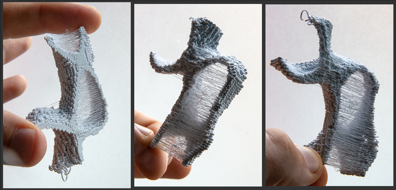
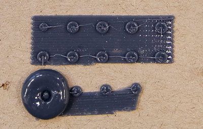
These shapes were created by defining some simple rules on how to interpret a given bitmap. No 3D models were used to 3D print these objects:
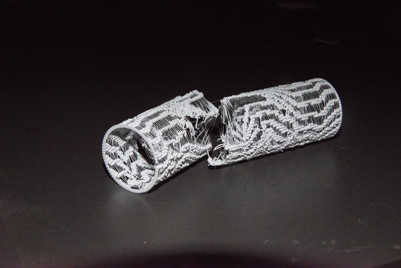
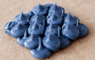
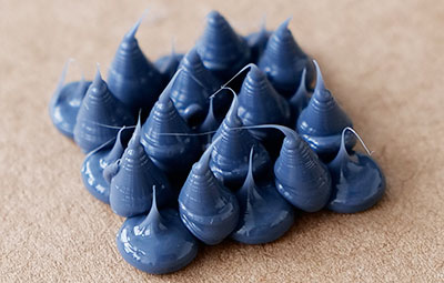
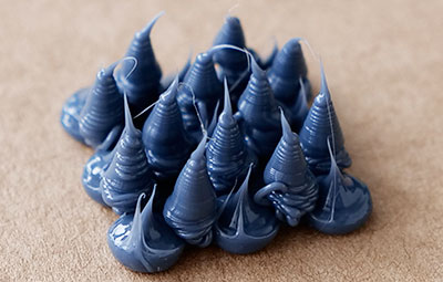
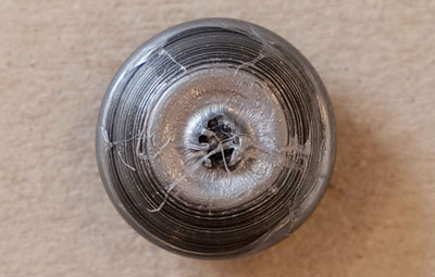
These objects were defined by a bitmap that was wrapped around a cylinder.
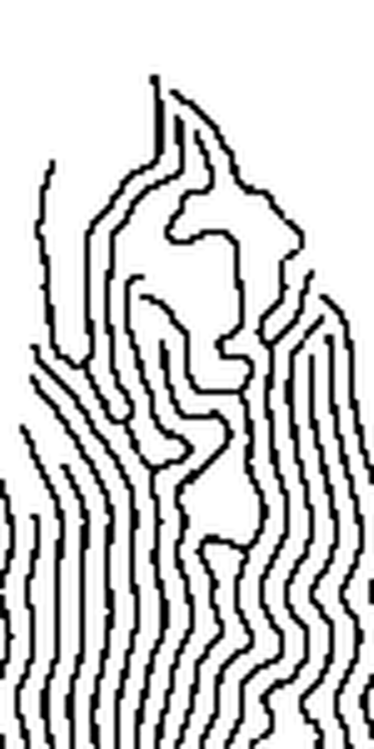
This is the bitmap that was used for the above objects. The pattern is a derivative of a Gray-Scott reaction-diffusion algorithm that was made tileable over the x-axis.
Using a gyroid like noise pattern, this small voxel-based structure was printed out of plastic drops by using a 3D bitmap for each layer.
This is the image collection that was used for the above object.
Creating a sponge like object:
 |
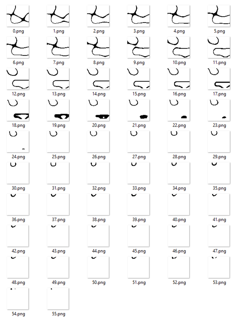
As a first test, I used the gcode from a flattened cube and added a single drop. |
|---|---|
 |
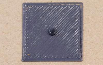
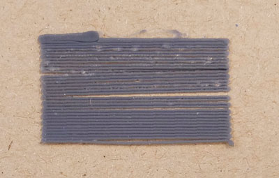
Three hardcoded rows with different extrusion amounts. |
 |
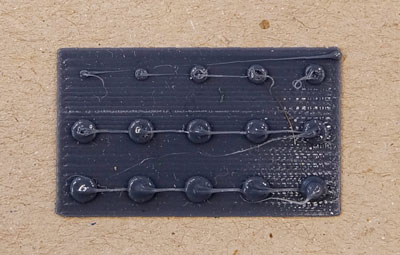
Three hardcoded row with equal extrusion amounts. The first drop seems to receive too little material. |
 |
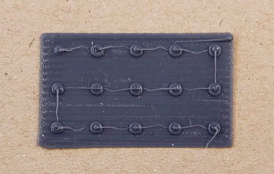
Extruding more material with a lower nozzle height. Oops! |
 |
Coordinates of the drops and the base didn’t lign up properly, so I decided to create a parametric base, instead of using the Gcode-output from a slicer. I followed the guide on creating G-code from Processing by CodePlastic. |
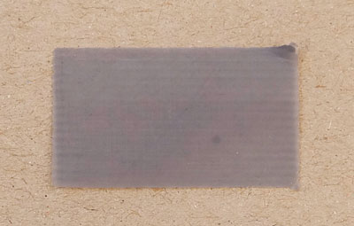 |
This one has about 0.1mm thickness. Too thin. |
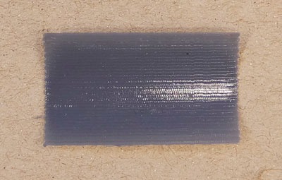 |
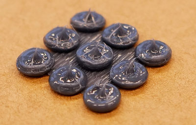
I settled on a base layer height of 0.14mm. |
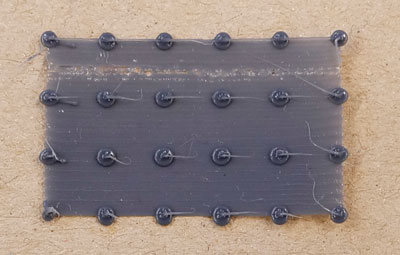 |
First parametric drops. Not priming material after retracting at the end of the previous print, created some under extrusion at the top of the test piece. |
 |
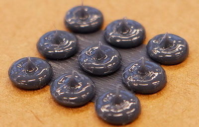
Fixed the under extrusion but made a mistake again when switching from absolute to relative extruder coordinates. |
 |
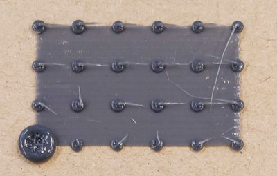
Smaller drops and more under extrusion. |
 |
Bigger drops and more under extrusion. |
 |
A first test with the second layer. I displaced the second layer in both X and Y, which made the new drops fall down to the base. |
 |
Just shifting the second layer on the Y axis, the new drop seem to rest on the two neighbouring ones. The drops seem to be pushed down too much. |
 |
Moving the nozzle heigher for the second layer, I hoped to prevent the drops from being pushed down, but the filament was ground away. |
 |
I cleaned the feeder motor bolt and lowered the extrusion speeds. I also doubled the extrusion amount for layer 2. |
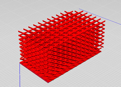 |
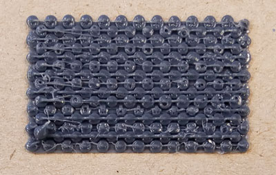
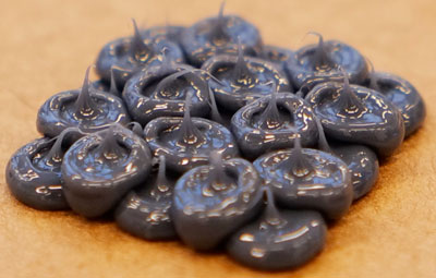
Making a taller object by stacking layers, shifting them half the size of a droplet (First no shift, then +X, then -Y, then -X, then back to the first XY position), to allow for cavities in the structure. |
 |
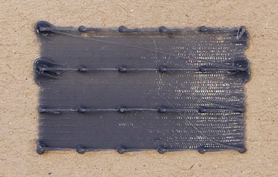
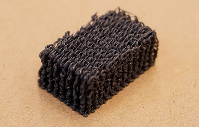
The top view looks pretty similar to the previous ones. |
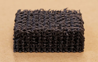 |
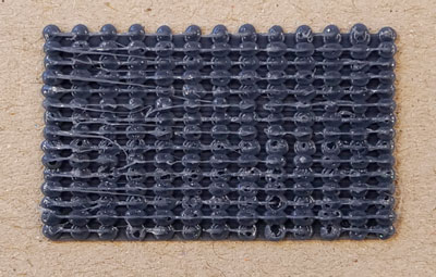
Maybe the shifting sequence allows for too much space, so the lines become squiggly. |
 |
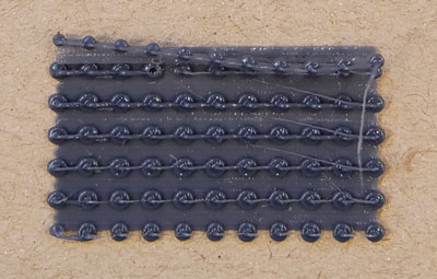
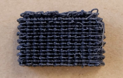
Still all by all a rather rectangular shape. Air can pass easily through it. |
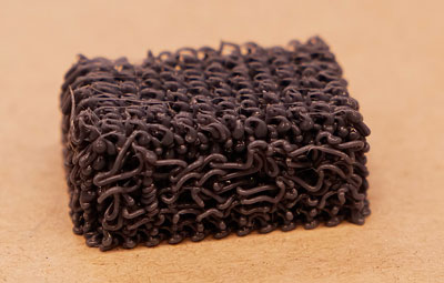 |
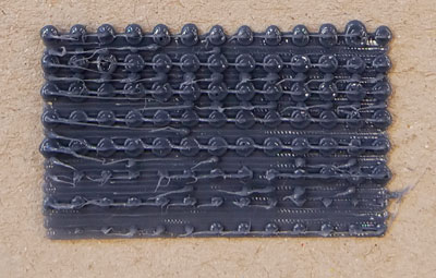
For some reason the backside turned out detached from the rest. The outsides are the exceptions of the shifting pattern. I’m curious how the inside looks like. |
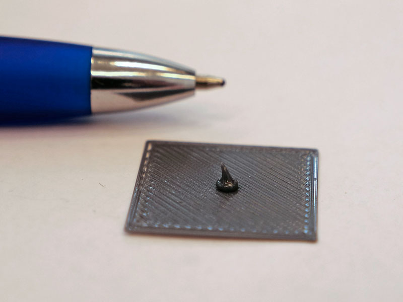
Bigger droplets:
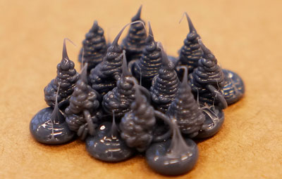
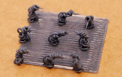 |
Extruding too little material while raising the Z-axis too fast and too far results in little chimney like structures. |
|---|---|
 |
Starting 1mm above the base, with 3mm extrusion. This is not yet enough material for the Z-height traveled. |
 |
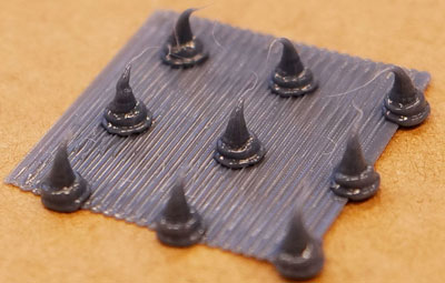
5mm extrusion this time. Still not enough. I waited 4 seconds after moving the nozzle up to let the tips cool down. This way they don’t bow down . |
 |
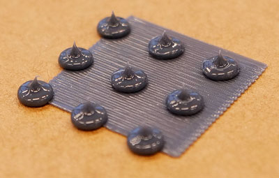
10mm material extrusion. The exstrusion is too fast and leaves a rough texture. |
 |
This is how it looks after the extrusion is slowed down |
 |
The first stacking test had a way too large z-height |
 |
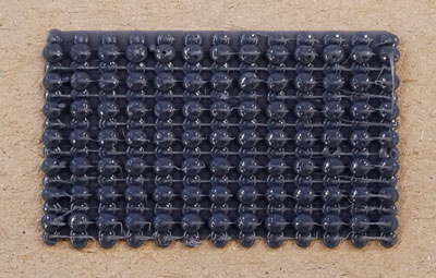
Corrected Z-height. Maybe this is a little too packed. There are almost no air pockets anymore. I could increase the droplet height or the grid size. |
 |
A droplet height of 3 instead of 2mm |
 |
A droplet height of 4mm |
 |
A droplet height of 5mm |
Single big blobs:
 |
By manually extruding copious amounts of plastic through a 0.8mm nozzle, a 3D printer can make very un-3D print like objects. |
|---|---|
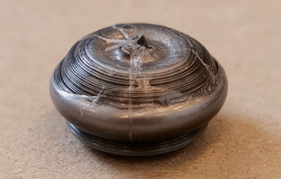 |
The shape seems to be determined by the cooling rather than by the plastic extrusion. |
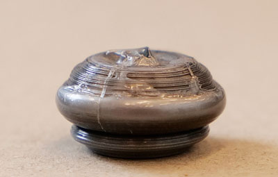 |
This could be the building block of new objects |
 |
In this test, we tried to keep the nozzle as deeply submerged in the plastic as we could. The plastic would be about a millimeter away from the heater element at all times. |
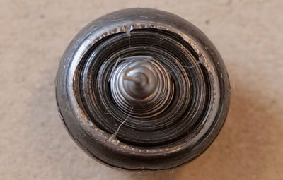
 |
These tests were done on a printbed at room temperature. Curious what a heated bed and automated extrusion and Z-axis motion will result in. |